

SCL 40A Automatic Transfer Switch Mains-Standby 3 Phase 400VAC – ATS40A3PHM-S
£964.06 Excl. VAT
SCL 40A Automatic Transfer Switch Mains-Standby 3 Phase 400VAC – ATS40A3PHM-S
Part No Description
ATS40A3PHM-S 40A Automatic Transfer Switch Mains-Standby 3 Phase 400VAC
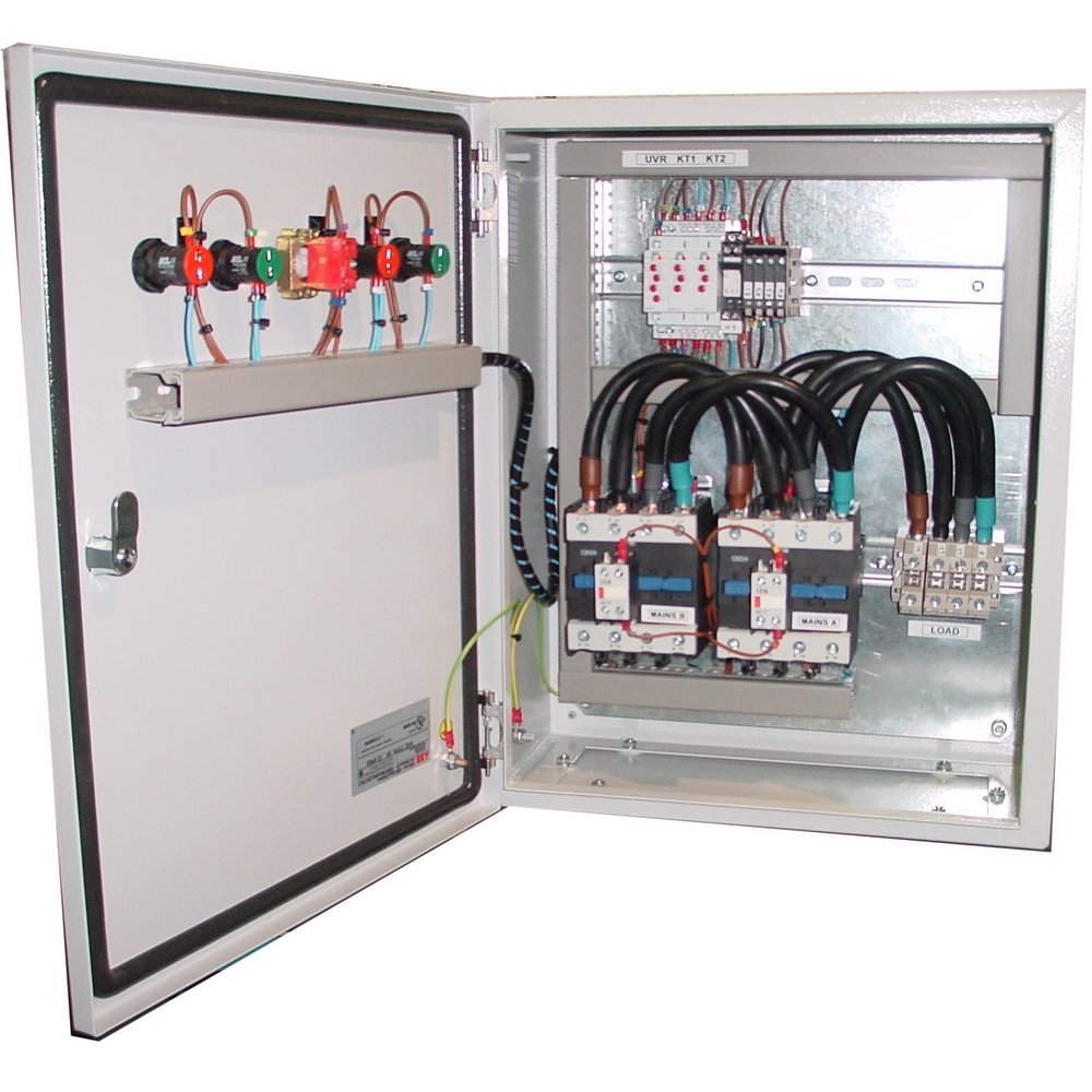
A range of ATS panels to be used where the local Mains (primary) supply is backed up by a generating* set or secondary power supply.
The ATS panel monitors the local Mains supply and will switch to the secondary if this should fail or fall outside pre-set limits. The ATS
panel controls the switching of the load from the Mains supply to the standby supply. On return of the Mains supply the ATS panel
will monitor it to ensure it is stable and then transfer the load from the standby back to the Mains supply. If the secondary supply is a
generator, at this point the ATS panel will request the generator to stop.
A phase failure relay is used for Mains voltage monitoring and offers under and over voltage protection as well as phase sequence. The
panel uses two timer relays to control timing functions in the panel. Timer one is used to control the Mains restoration period, this
controls the period the Mains supply has to be healthy before engaging the Mains contactor. Timer two controls the standby settling
period, this timer is useful for situations when the standby supply is a generator as it ensures the generator has ran up to speed and
stabilized before a load is applied to the generator.
The default setting for the primary Mains restoration period is one minute and timer two is set for 15 seconds. (Both are fully adjustable).
The generator start signal is by means of volt free normally open (N/O) contact closing when the generator is required to run.
A two position selector switch is used for control. In the AUTO position all operations are automatic with the panel switching to the
standby supply when there is a failure of the primary Mains supply. The second position – TEST – switches the load to the secondary supply
(The start signal is given to the generator).
Cable entry as standard is arranged for bottom entry with a direct connection into the contactors. A 16A auxiliary output is provided for
use with battery chargers, water jacket heaters etc.
*The Generator is required to have a 2 wire start / Auto start facility
Single Phase ATS
Mechanically & Electrically interlocked contactors
AC1 rated contactors to BS EN 60947-6-1
Removeable top and bottom gland plates
IP65 Enclosure
Auto / Manual tests switch
Designed for Mains – Generator or Mains – Mains
Two wire generator start
Configurable timers
Panel status LED indicators
Custom designs available
Enclosure Dimensions: 400 x 300 x 200mm
* Also available up to 1250 Amp
Description
SCL 40A Automatic Transfer Switch Mains-Standby 3 Phase 400VAC – ATS40A3PHM-S
Part No Description
ATS40A3PHM-S 40A Automatic Transfer Switch Mains-Standby 3 Phase 400VAC
A range of ATS panels to be used where the local Mains (primary) supply is backed up by a generating* set or secondary power supply.
The ATS panel monitors the local Mains supply and will switch to the secondary if this should fail or fall outside pre-set limits. The ATS
panel controls the switching of the load from the Mains supply to the standby supply. On return of the Mains supply the ATS panel
will monitor it to ensure it is stable and then transfer the load from the standby back to the Mains supply. If the secondary supply is a
generator, at this point the ATS panel will request the generator to stop.
A phase failure relay is used for Mains voltage monitoring and offers under and over voltage protection as well as phase sequence. The
panel uses two timer relays to control timing functions in the panel. Timer one is used to control the Mains restoration period, this
controls the period the Mains supply has to be healthy before engaging the Mains contactor. Timer two controls the standby settling
period, this timer is useful for situations when the standby supply is a generator as it ensures the generator has ran up to speed and
stabilized before a load is applied to the generator.
The default setting for the primary Mains restoration period is one minute and timer two is set for 15 seconds. (Both are fully adjustable).
The generator start signal is by means of volt free normally open (N/O) contact closing when the generator is required to run.
A two position selector switch is used for control. In the AUTO position all operations are automatic with the panel switching to the
standby supply when there is a failure of the primary Mains supply. The second position – TEST – switches the load to the secondary supply
(The start signal is given to the generator).
Cable entry as standard is arranged for bottom entry with a direct connection into the contactors. A 16A auxiliary output is provided for
use with battery chargers, water jacket heaters etc.
*The Generator is required to have a 2 wire start / Auto start facility
Single Phase ATS
Mechanically & Electrically interlocked contactors
AC1 rated contactors to BS EN 60947-6-1
Removeable top and bottom gland plates
IP65 Enclosure
Auto / Manual tests switch
Designed for Mains – Generator or Mains – Mains
Two wire generator start
Configurable timers
Panel status LED indicators
Custom designs available
Enclosure Dimensions: 400 x 300 x 200mm
* Also available up to 1250 Amp
Additional information
| Dimensions | 400 × 300 × 200 cm |
|---|
Related products
-

SCL 125A Automatic Transfer Switch Mains-Standby 1 Phase 240VAC – ATS125A1PHM-S
£1,272.54 Excl. VAT Add to basket -

SCL 63A 4 Pole Metal Enclosed Changeover Switch IP65 – NTCI0063
£152.04 Excl. VAT Add to basket -
Axiom DOL Starter 3 Phase AC3 – 5.5kW 7.5HP 12A 440V – TEW11A9
£22.43 Excl. VAT Add to basket